The first part of this NSX-T and Kubernetes series of post was about the setup of kubernetes on Ubuntu server using docker.
This part will focus on the configuration of NSX-T Controller.
NSX-T and Kubernetes Configuration
In order to add a Kubernetes cluster to an NSX-T controller, we will need to set up a lot of objects like: IP Pools, IP Block, Overlay Transport Zone, Edge cluster, Tier-0 Router, segment, Load Balancer Service, Firewall Marker and admin account.
Let’s start !
Edge Cluster / Tier-0 router / Tier-1 router
As we will use source NAT applied to the Tier-0 router, this one must not be deployed as “Active/Active” on the NSX Edge cluster.
Therefore you may need to deploy another NSX-Edge Cluster and create a new Tier-0 router in Active/Passive mode.
Also create a Tier-1 router and link it to this Tier-0, the Tier-1 router will attach the load balancer service.
See this post on how to create an Edge cluster and Tier-0/Tier-1 router
Segment / Logical Switch
We have create a segment / Logical switch in the overlay transport zone for pod communication trafic between worker/master nodes.
The second network card of our kubernetes nodes (ens192) will connect to this segment.
see this post on how to create a segment.
Connect the segment to the kubernetes nodes second network card using the vsphere client (you can also do it directly on the segment page on NSX).
In the Simplified UI go to “Segments” and edit your previously created segment. The segment here is “k8s02-ls”


Click the “PORTS” dropdown list to show the number of ports connected to this segment. If there still 0 you may have to wait a little longuer as the simplified UI is not real time. Then you should see at least three ports connected.
Edit All ports and set these tags:
- scope: ncp/cluster | tag: your cluster name (here k8s02)
- scope: ncp/node_name | tag: node name
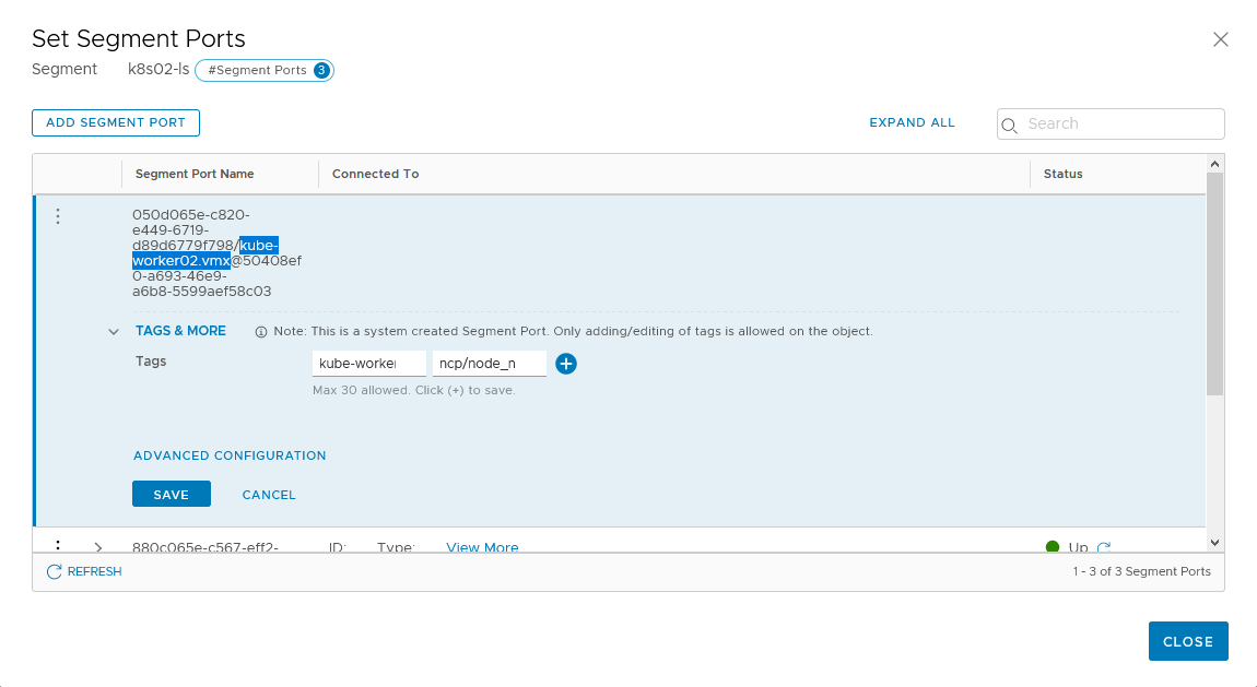
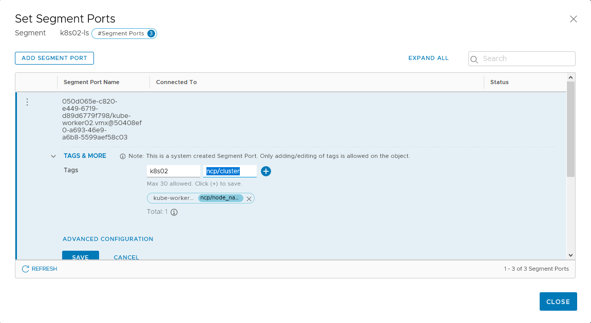
The node_name must be the same as the hostname of the kubernetes nodes.
The cluster name must be the same for all node in the kubernetes cluster and we will use it when apply the deployment on the master node.
In this case we will have:
- For kube-master01
- scope: ncp/cluster, tag: k8s02
- scope: ncp/node_name, tag: kube-master01
- For kube-worker01
- scope: ncp/cluster, tag: k8s02
- scope: ncp/node_name, tag: kube-worker01
- For kube-worker02
- scope: ncp/cluster, tag: k8s02
- scope: ncp/node_name, tag: kube-worker02
Overlay Transport Zone
The overlay transport zone will allow communication between pods and the Tier-1 gateway through segment (logical switch) created automatically by the nsx control plane.
Services like Load Balancer virtual servers will be created automatically, communication between pods and load balancer or pods located on differents workers will go through geneve tunnel.
The overlay transport zone must be the same as the one used by the ESXi hosts.
See this post on how to create a Transport Zone
IP pools and blocks
We will need several IP Pools and blocks.
The first one is the “container_ip_blocks” which is the “pod-network-cidr” we didn’t configure before on the kubeadm init.
The second one is the “external_ip_pools” for SNAT on Tier-0 router.
The last one is the “external_ip_pools_lb” for load balancer virtual server IP Address.
Let’s create the block. In the Simplified UI go to “Networking”, “IP ADDRESS BLOCKS” and click “ADD ADDRESS BLOCKS” button.

Just put the name of the block and the subnet in the CIDR format and click “SAVE”. Thus my container_ip_blocks will be 172.26.0.0/16, this will be the pod global network.
Every namespace on the kubernetes cluster will have a /24 from this subnet.
Let’s create the pools. In the Simplified UI go to “Networking”, “IP ADDRESS POOLS” and click “ADD ADDRESS POOL” button.

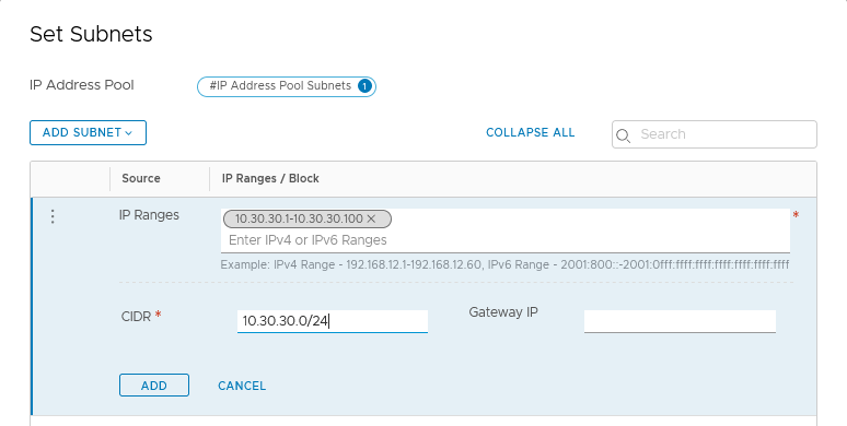
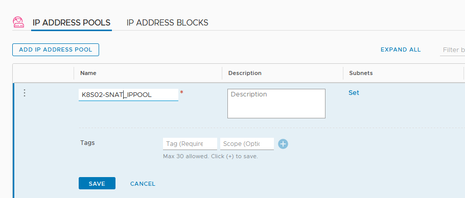
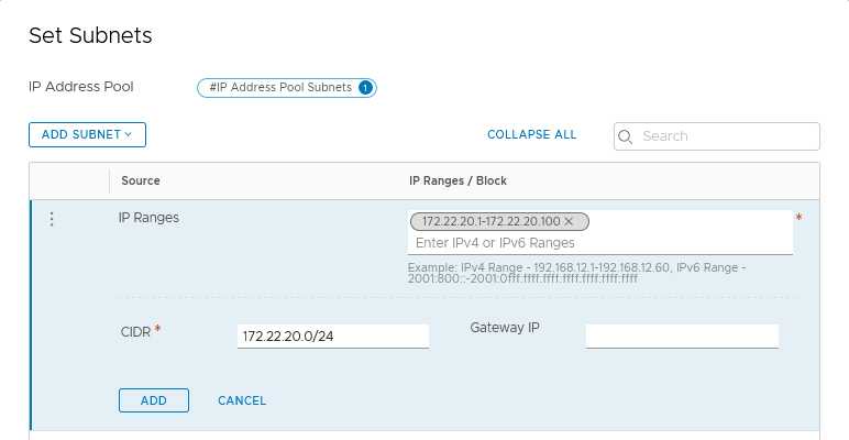
Name the pool and click “Set” under Subnet to add an IP Range and the corresponding subnet.
Load Balancer virtual server will have IP addresses on the 10.30.30.1 to 10.30.30.100 range.
For SNAT we will use IP Addresses from 172.22.20.1 to 172.22.20.100 for each /24 subnet from the container_ip_blocks.
Load Balancer
A Load balancer service will allow the creation of load balancer virtual server. A Tier-1 router must attach the load balancer service in order to be up and running.
If created In the Simplified UI the load balancer service is not visible from the kubernetes cluster, we have to create it from the old fashion UI.
In the “Advanced Networking & Security”, click “Load Balancers” under “Networking” and clic “ADD” button
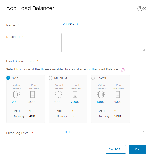
Name the Load Balancer service, choose the Size, beware that the size of the load balancer must be lower or equal to the size of the NSX-Edge where the Tier-1 router is located.
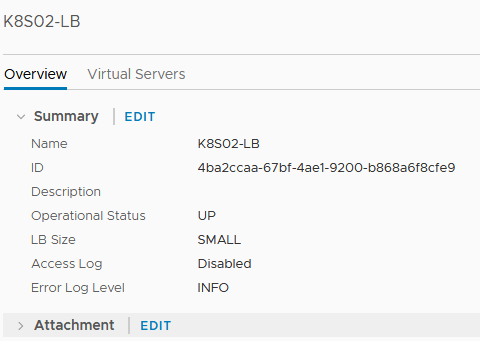
Once created, click the name of the load balancer to show all details, then click “EDIT” next to “Attachment”
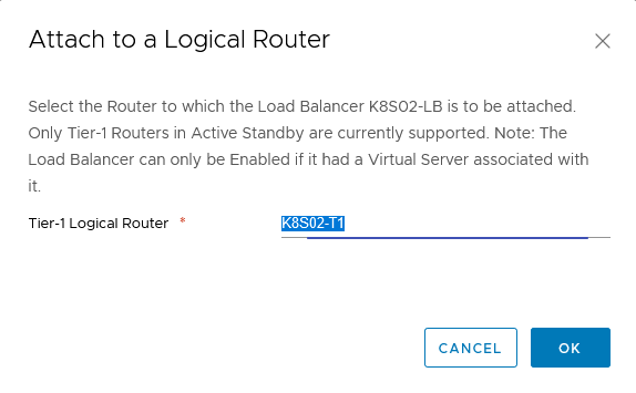
Choose the right Tier-1 router and click “OK”.
Firewall marker
In order to create firewall rules automatically on the distributed firewall, the, we must provide a top and bottom marker for the NSX control plane.
In the Simplified UI go to “Security”, “Distributed Firewall” and click the “CATEGORY SPECIFIC RULES” tab, Click “ADD POLICY” to create two policies.
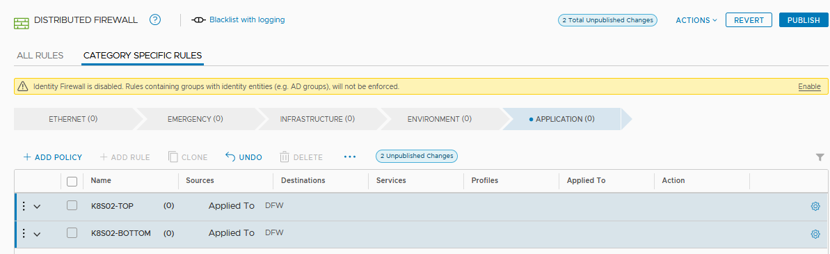
Name the two firewall policies and click the “PUBLISH” button in the up right corner.
Retrieve IDs
To configure the NSX control plane on the kubernetes cluster, we can use the name of all objects created previously however i prefer the use of IDs.
IDs will never change unless we delete the object, change of name is possible on all object and could broke the configuration.
As some retrieval of ID is not possible on the simplied UI, we must use the old fashion UI localized in the “Advanced Networking & Security” Tab.
Retrieve IP pool ID
In “Advanced Networking & Security” go to “Groups” then the IP Pools tab, click on the ID column to show the IP pood ID and copy it.
Retrieve IP blocks ID
In “Advanced Networking & Security” go to “IPAM” under “Networking” and click on the ID column to show the IP block ID and copy it.
Retrieve Load balancer servive ID
In “Advanced Networking & Security” go to “Load Balancing” under “Networking” and click the load balancer name to get the ID.
Retrieve Tier-0 router ID
In “Advanced Networking & Security” go to “Routers” under “Networking” and click the ID column of the router and copy it.
Retrieve Overlay Transport Zone ID
In “System” tab, go to “Transport Zone” under “Fabric” and click the ID column of the Overlay transport zone
We have all needed informations:
| Type | Name | NSX-T Variable | ID |
|---|---|---|---|
| IP Block | K8S02-IP_BLOCKS | container_ip_blocks | 0c99b7ea-7d74-4763-8e3e-ba79a0619f3e |
| IP Pool | K8S02-SNAT_IPPOOL | external_ip_pools | b49e44b9-6433-4b61-a8a2-c764fe2fd859 |
| IP Pool | K8S02-LB_IPPOOL | external_ip_pools_lb | 6c6e6f36-75c6-4493-9791-7f29e1179cf8 |
| TIER-0 Router | K8S02-T0 | top_tier_router | 3d757cf9-1111-4fb8-ac89-d6a4abb73c5c |
| Overlay | Overlay-TZ | overlay_tz | e8bbadc9-cd84-42f3-b28e-07ce585ed0c3 |
| Load Balancer | K8S02-LB | lb_service | 4ba2ccaa-67bf-4ae1-9200-b868a6f8cfe9 |
| Firewall Marker | K8S02-TOP | top_firewall_section_marker | 81a84999-2114-4cec-bbb8-58d3a9eca1ed |
| Firewall Marker | K8S02-BOTTOM | bottom_firewall_section_marker | 84b62ad6-d395-4043-87ce-1d982f88eb03 |
| Edge Cluster | nsx-edge-cluster03 | edge_cluster | d83f08b6-0d13-45f5-8271-f1609831b6ee |
We have successfully prepared our NSX-T manager for Kubernetes operations.
See the vmware documentation about NSX-T and Kubernetes: NSX-T Documentation
That’s it !, i hope you found something useful. See you on Part 3